|
Assembling your own android finger
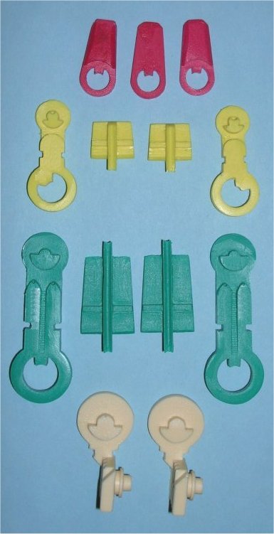
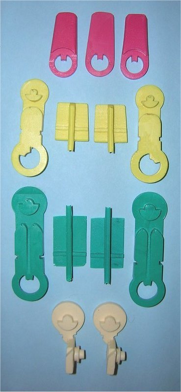
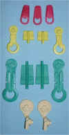
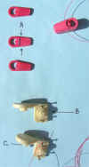
1. Verify that you have received all of the parts. Each
finger consists of 13 bone segments.
This end of each picture is
the outer end of each finger.
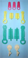
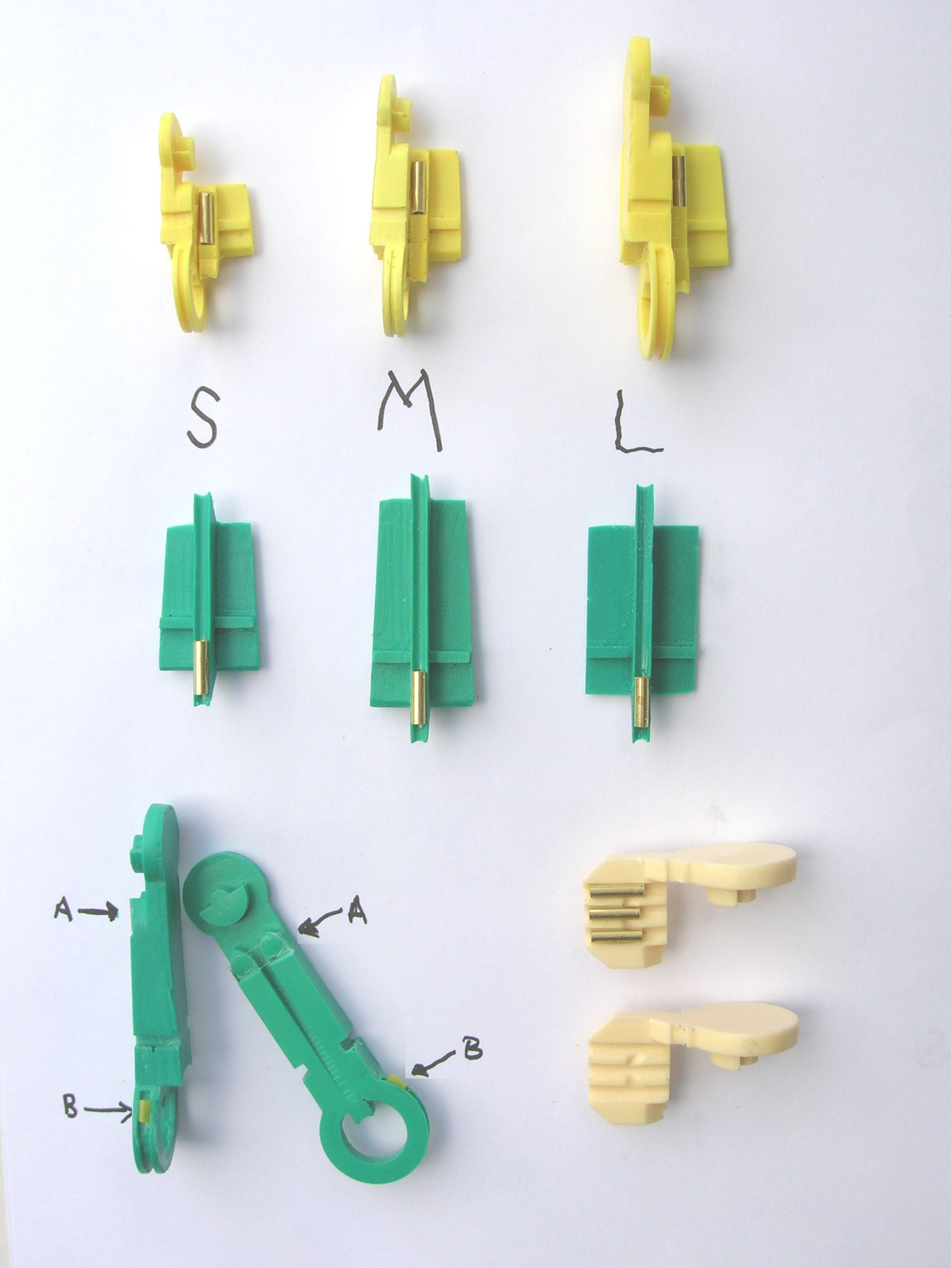
Small
Medium
Large
This end of
each picture is the palm end of each finger.
- 3 red parts are the finger tip (also called the distal
segment)
- 4 yellow parts are the medial segment
- 4 green parts are the proximal segment
- 2 white parts are the knuckle (the same for all finger
sizes)
2. You should also have the following parts:
- Cables
- 2 - yellow cables (5 feet long)
- 2 - green cables (5 feet long)
- 2 - clear cable (5 feet long)
- 1 - red cable (10 feet long) (total 7 cables)
- Guides
- 1 - 3/32 brass tube - 5 inches long
- 1 - clear plastic sheet - 1/2 x 1/2 inch
- 1 - 1 inch 1/16" plastic tubing
- Hardware
- 8 - small wood screws (size #00) (+2 spares)
- 4 - small washers (+1 spare)
- 2 - machine screws 1/2 inch x 0-80
- 4 - nuts (+1 spare) 0-80
- Mounting parts
- 1 - aluminum bar (4 inches long)
- 2 - 4-40 screws - 1 1/4 inches long
- 1 - 5/32 inch aluminum tube - 3 inches long
(* updated *)
- 2 - nuts (4-40)
- 2 - lock washers (4-40)
- Tools provided
- 1 - 1/32 inch drill bit (one per order)
- 1 - 1 mm drill bit (one per order)
3. Collect the other tools you will need
- 10" x 1" metal file
- 8" triangular metal file about 1/4" x 1/4" x
1/4"
- several different needle files - best is a 3 mm x 140 mm set (10
files)
- small hacksaw with a very thin blade for cutting tubing
- normal sized hacksaw for cutting aluminum bar stock.
- electric drill with a small chuck to handle the small drills
- tube of super glue GEL - USE ONLY THE GEL KIND (from a hobby
shop)
- set of tiny screwdrivers
- ruler which reads in mm and inches.
- razor blade - for cutting
- pair of normal sized pliers - for crimping.
- vise to hold brass tubing while cutting it (should have
"V" in face)
- some toothpicks
- 1/16" metal drill bit.
- 1/8" metal drill bit.
- 15/64" metal drill bit
Begin work here:
1. Cut and file the cable
guides
- Cut 5 pieces of 3/32 brass tubing each 3/8" long.
- Use the small hacksaw with a very thin blade
- Technique: cut only on the back stroke i.e. with the
teeth backwards.
- File both ends smooth
- Use round file to file inside both ends to remove any burrs.
- Cut 2 small pieces of clear plastic sheet.
- Cut 2 pieces of 1/16" plastic tubing each 1/8" (3 mm)
long.
- Technique: cut with razor blade
- Cut 5 (1 spare) pieces of 3/32 brass tubing each 1/8"
long
- Use the small hacksaw with a very thin blade
- Technique: cut only on the back stroke i.e. with the
teeth backwards.
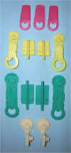
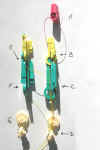
2. Attach the 9 cable guides. Refer to the
following picture.

- #1 - Pick a yellow top or bottom (the smaller pieces)
- The guide will be glued about 1/8" from the OUTER end of the
piece.
- Put a tiny amount of superglue in the center curved area
1/4" from outer end.
- Use a toothpick to smear it around a little.
- Place one of the 3/8" guides in the glue.
- Use the edge of a razor blade to it hold down until the glue
sets.
- See above picture.
- #2 - Pick a green top or bottom (the smaller pieces)
- The guide will be glued about 1/8" from the INNER end of the
piece.
- Repeat above gluing procedure.
- See above picture.
- #3, #4, #5 - Pick a white knuckle piece.
- Glue the guides in the center of each trough.
- Use the gluing procedure given above.
- See above picture.
- #6, #7 - Pick both green side pieces.
- Repeat the following for both pieces.
- Use the 1/4" wide triangular file to file area "A"
in the picture.
- File about 5 mm wide and only deep enough to hide the 11 x 4 mm
plastic.
- After filing remove any burrs and dust.
- Put two TINY dabs of super glue on the green piece where you
filed it down.
- Place the 11 x 4 mm piece of plastic on the green part as shown
above ("A").
- #8, #9 - Pick both green side pieces.
- Repeat the following for both pieces.
- Use a tiny round file to file area "B" in the picture
about 1/8" from flat area.
- The goal is to make the 1/8" long plastic tube fit there.
- After filing remove any burrs and dust.
- Put one TINY dab of super glue on the green piece where you filed
it down.
- Use a toothpick to smear it around.
- Place a 1/8" piece of 1/16" tubing 1/8" from the
flat part of the piece as in "B"
- Use the edge of a razor blade to it hold down until the glue
sets.
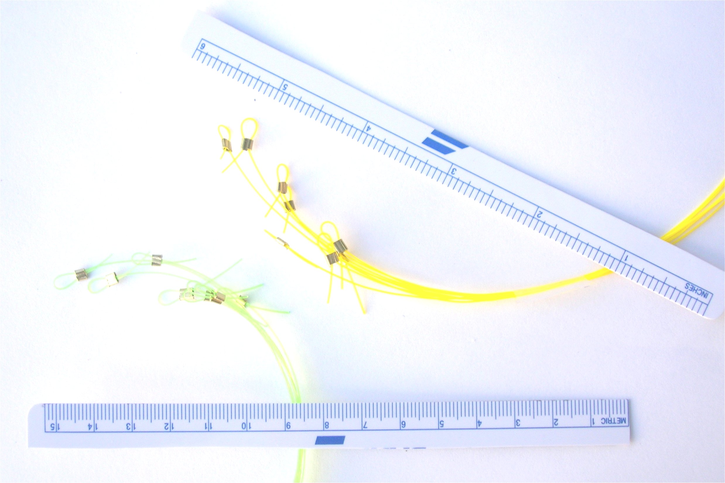
3. Prepare the yellow & green cables. Refer
to the following picture.

- Repeat the following for each of your 2 yellow cables and 2
green cables.
- Pick a 1/8" piece of 3/32" brass tubing (cut in #1
above)
- Pass about 1 inch of cable through the tubing.
- Make a loop and pass the cable back through the tubing again.
- Adjust the loop to about 3/16" in diameter.
- Use your pliers to crimp (squeeze) the tubing flat over the cable.
- This will hold the cable in place.
4. Make final adjustments to parts so that they move easily.
Refer to the following picture.
- Red distal parts.
- Assemble the three RED parts and hold them in one hand
- Assemble the 4 yellow parts and hold them in the other hand.
- Verify that the inner end of the RED parts fits easily between
the YELLOW parts.
- If not, then file down the flat sides of the red parts until they
do fit easily.
- Technique: hold flat side against 10" file and rub
against file (file it)
- Be sure to check that the outer ends of the YELLOW side pieces
(circular areas) move without much friction inside the RED tip parts.
- If not, then file down the YELLOW circular outer ends a little.
- Yellow medial parts
- Assemble the 4 yellow parts and hold them in one hand.
- Assemble the 4 green parts and hold them in the other hand.
- Verify that the inner ends of the yellow parts fits easily between
the green parts
- Be sure to check that the outer ends of the green side pieces
(circular areas) move without much friction inside the yellow parts.
- If not, determine where the friction is and file that area.
- Repeat until parts move easily.
- Green proximal parts
- Assemble the 4 green parts and hold them in one hand.
- Assemble the 2 white parts and hold them in the other hand.
- Verify that the inner end of the green parts fits easily between
the white parts
- Be sure to check that the outer ends of the white knuckle pieces
(circular areas) move without much friction inside the green parts.
- If not, determine where the friction is and file that area.
- The front pointing end of the top & bottom pieces need to be
filed down a little on both sides so that they do not rub against
the yellow parts (open ends).
- Repeat until parts move easily.
- White knuckle parts
- File the corners off the parts as shown in the above
picture.
- This is done so that the parts can turn freely in the mounting.
- Also this is needed if you want to mount several fingers close
together.
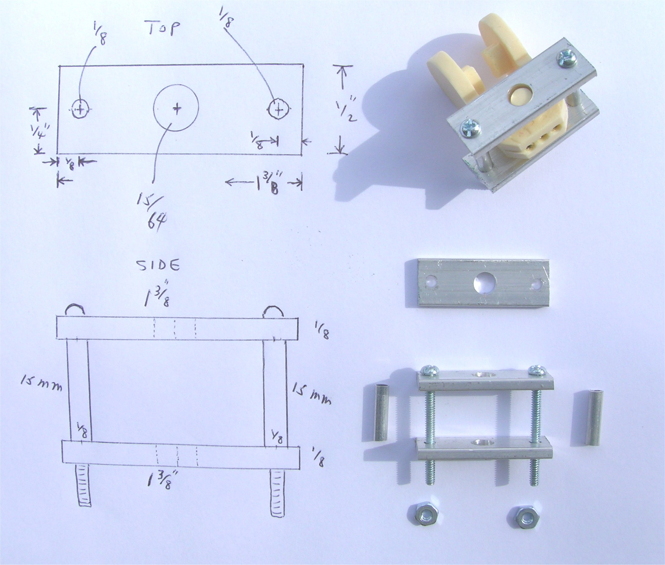
5. Build mounting Refer
to the following picture.
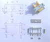
- Select the 4" aluminum bar (1/2" x 1/8" x 4")
- Cut 2 pieces 1 3/8" long using normal hacksaw.
- Use 10" metal file to file the ends even.
- Technique: clamp both parts in vise and file at the same
time.
- Use a black felt tipped pen to mark the centers as shown in the
above picture.
- Clamp one 1 3/8" piece in your vise.
- Use your 1/8" drill bit to drill the two holes 1/8"
from the ends (see picture)
- Use your 15/64" drill bit to drill the one hole in the
center of the bar (see picture)
- Use 10" file to remove burrs from the back.
- Repeat for the second piece.
- Technique: clamp both parts in vise and drill through
holes in first piece
- Select the 5/32" aluminum tube - 3 inches long
(* updated *)
- Cut 2 pieces each 15.5 mm long.
- File both ends flat and file length down to 15 mm
- Repeat for second piece.
- Assemble mounting as shown in above picture - with screws, nuts,
and lock washers.
6. Attach cables. Refer
to the following pictures.
- Red cable (above left picture)
- Select the center red finger tip piece.
- Select the 1/32" drill bit.
- Drill 1/32" hole in center of finger tip as shown in
"A" above.
- Be very careful not to break the drill bit.
- Select the 10 foot long red cable.
- Pass the cable through the hole and move the part to middle of
the cable.
- Put a tiny dab of superglue into the hole and on the cable to
hold it in place.
- Use a toothpick to push glue into the hole.
- Use superglue to glue the three red parts together.
- Technique: glue center piece and one side piece.
Then glue the second side piece later.
- Be sure that the open ring ends line up exactly.
- Yellow cables (above right picture)
- Select one yellow top (or bottom) piece and one yellow side
piece.
- Place top (or bottom) piece in notch of side piece.
- Side piece - be sure open end is on inside closest to center of
top piece.
- Be sure to press the top piece firmly against the side piece.
- Select the 1 mm drill bit.
- On the top piece, mark the spot to drill at 3mm in and about
half way from the front to back of the piece (see above right
picture)
- Drill a 1 mm hole down through the top piece into the side piece.
- Hole depth should be about 1/4"
- Remove drilled out material from between pieces and clean if
necessary.
- Select a #00 small 1/4" wood screw and a small washer.
- Put the washer on the screw and put both in the top part.
- Screw in part way only using tiny screwdriver.
- Select one yellow cable assembly.
- Slip loop under the washer.
- Maintain tension on the cable as you screw down the screw pinning
the cable under the washer against the top piece.
- Trim the unneeded end of the cable.
- Repeat with the remaining yellow cable and top and side
pieces.
- Green cables (above right picture)
- Select one green top (or bottom) piece and one green side
piece.
- Place top (or bottom) piece in notch of side piece.
- Side piece - be sure open end is on inside closest to center of
top piece.
- Be sure to press the top piece firmly against the side piece.
- Select the 1 mm drill bit.
- On the top piece, mark the spot to drill at 3mm in and about
half way from the front to back of the piece (see above right
picture)
- Drill a 1 mm hole down through the top piece into the side piece.
- Hole depth should be about 1/4"
- Remove drilled out material from between pieces and clean if
necessary.
- Select a #00 small 1/4" wood screw and a small washer.
- Put the washer on the screw and put both in the top part.
- Screw in part way only using tiny screwdriver.
- Select one green cable assembly.
- Slip loop under the washer.
- Maintain tension on the cable as you screw down the screw pinning
the cable under the washer against the top piece.
- Trim the unneeded end of the cable.
- Repeat with the remaining green cable and top and side
pieces.
- White cables (above left picture)
- Select one white knuckle piece.
- Select the 1/32" drill bit.
- Drill through the center of the round center section just above
the flat part of the piece from the "B" direction - the
palm end of the part.
- Be careful not to break the drill bit.
- Remove drilled out material and clean if necessary
- Select one clear cable.
- Insert the clear cable through the hole just drilled from
direction "C".
- Tie the cable in place with the knot as shown in "C" (I
used RED cable so you could see it clearly).
- Trim the unneeded end of the cable.
- Repeat with the remaining clear cable and knuckle piece.
- Assemble the two knuckle piece with the guides in the center.
- Select the 1/16" drill bit.
- Mark the spot to drill at 2 mm in from the side (of rectangular
flat part) and in the center from the front to the back (see above left picture)
- Drill a 1/16" hole down through both parts.
- Select a 0-80 screw 1/2" long and insert through the hole
just drilled.
- The purpose is to keep the parts correctly lined up.
- Drill another 1/16" hole on the other side of the part (see
above left picture)
- Remove drilled out material from between parts and clean if
necessary.
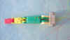
7. Threading the cables through the parts. Refer
to the following picture.
- Line up your parts as shown above.
- You will notice that the yellow parts (above) are inside the green parts.
- You will need to loosen the screws in the green parts
- Take the green top (or bottom) off
- Thread the green cable through the 1/8" tiny plastic tube guide on the top of the green side piece.
- Thread the yellow cable under the clear plastic cable guide from the round end toward the open end of the green side part.
- Put the yellow open end over the green outer round end.
- Make sure the yellow cable is aligned in the grove of the yellow open end.
- Put the green top (or bottom) back on
- And screw the screw, washer, and cable back on as before.
- Repeat with both sets of yellow & green parts as shown above.
- Threading the RED cable.
- Pick both ends of the red cable.
- Pass them both through the brass cable guide on the yellow part.
- The direction would be from the outer end to the inner end of the brass guide.
- Pass them both through the brass cable guide on the green part.
- The direction would be from the outer end to the inner end of the brass guide.
- Pass them both through the center cable guide on the white knuckle part.
- The direction would be from the outer end to the inner end of the brass guide.
- Finally place the red finger tip over the yellow outer end
and gently press the red cables close around the tip so that they do not block the yellow parts.
- Threading the yellow cables
- Pass the yellow cable though the brass cable guide on the green part.
- The direction would be from the outer end to the inner end of the brass guide.
- Pass the yellow cable through the center cable guide on the white knuckle part.
- The direction would be from the outer end to the inner end of the brass guide.
- Repeat with the second yellow cable.
- Threading the green cables
- Make sure the green cables pass through the 1/8" tiny plastic guides
- Turn the white knuckle part with the 3 brass guides so that the guides are facing upward and the large round part is toward the green parts.
- Thread the green cable through the outer brass guide which is closest to it.
- The direction would be from the outer end to the inner end of the brass guide.
- Repeat with the second green cable using the other empty cable guide.
- You should now have 6 cables passing through the white knuckle part - 2 green, 2 yellow and 2 red.
- Threading the clear cables
- Simply make sure that one clear cable goes around the center to the left and the other clear cable goes around the center to the right.
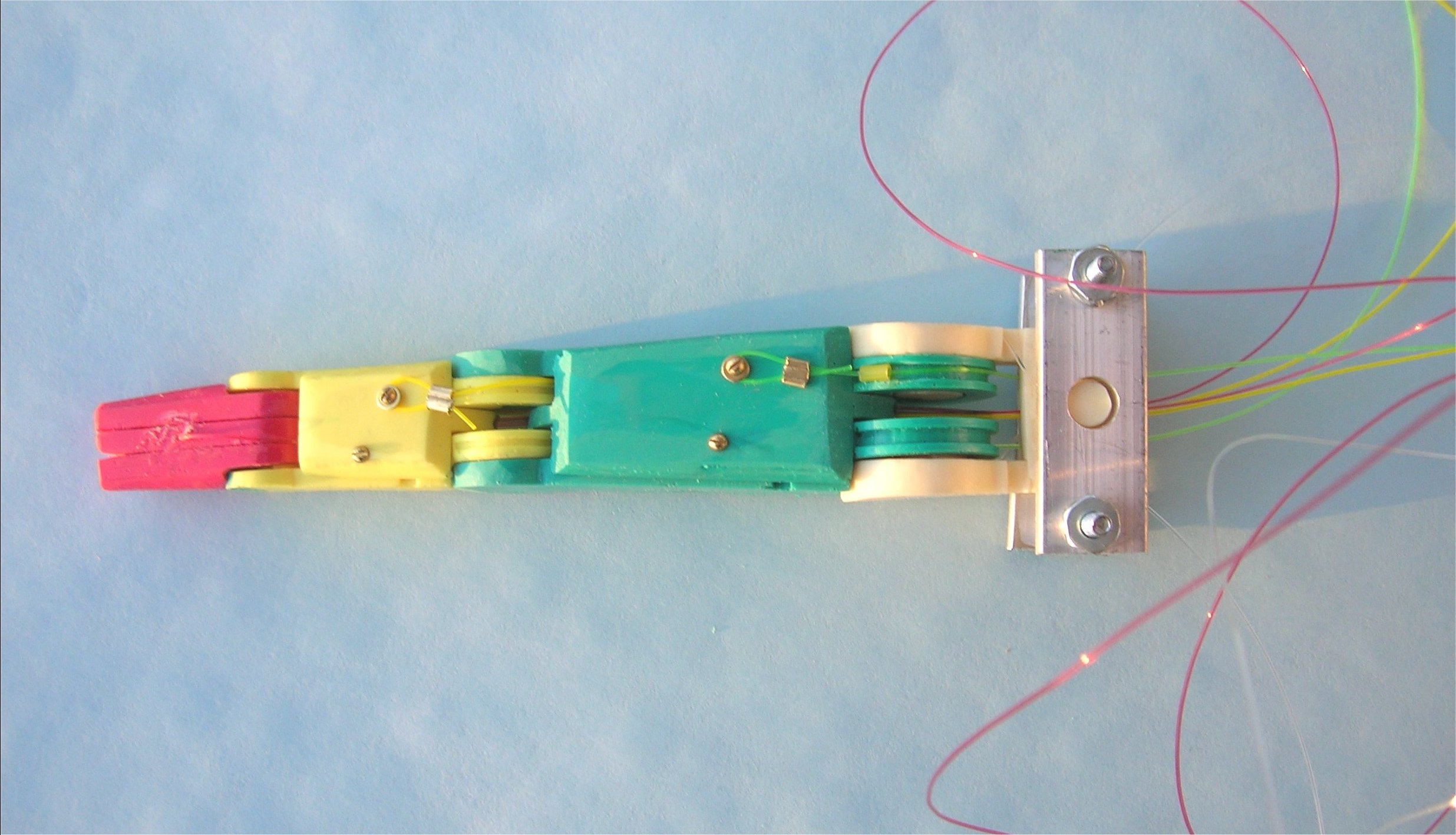
8. Putting the finger together. Refer
to the following pictures.
- You should now have all your cables threaded through the cable guides.
- If not, go back to previous section and recheck your work.
- The red tip should be placed on the yellow medial part.
- Combine the left half (above left picture) with the right half.
- Place the left yellow & green pieces onto the right yellow & green pieces.
- Make sure the tops & bottoms fit into the notches.
- Insert the white knuckle piece with the cables into the proper green open end.
- Insert the other knuckle piece into the other green open end
- Now your finger should look like the right picture (except for the mounting)
- Final testing
- Make sure that all segments move easily
- If not, find the areas of friction and file a little off the rubbing areas.
- Drilling and finishing the yellow parts.
- Be sure that you press the yellow sides together
- This will guarantee that the yellow segment fits easily into the green segment
- Select the 1 mm drill bit.
- On the top piece, mark the spot to drill at 2mm in and about half way from the front to back of the piece (see above right picture)
- Drill a 1 mm hole down through the top piece into the side piece.
- Hole depth should be about 1/4"
- Remove drilled out material from between pieces and clean if necessary.
- Select a #00 small 1/4" wood screw.
- Put the screw in the top part.
- Screw in part way only using tiny screwdriver.
- Turn the finger over and repeat the above for the other side.
- Now that both holes are drilled out and cleaned, you screw in both of the screws all of the way.
- Drilling and finishing the green parts.
- Be sure that you press the green sides together
- This will guarantee that the green segment fits easily into the knuckle segment
- Select the 1 mm drill bit.
- On the top piece, mark the spot to drill at 3mm in and about 1/2 inch from the back end of the top (see above right picture)
- Drill a 1 mm hole down through the top piece into the side piece.
- Hole depth should be about 1/4"
- Remove drilled out material from between pieces and clean if necessary.
- Select a #00 small 1/4" wood screw.
- Put the screw in the top part.
- Screw in part way only using tiny screwdriver.
- Turn the finger over and repeat the above for the other side.
- Now that both holes are drilled out and cleaned, you screw in both of the screws all of the way.
- Assembling the knuckle
- Insert both knuckle pieces into the proper green pieces.
- Make sure you have the corners filed off as described above.
- Select a 0-80 screw 1/2 inch long.
- Select 2 0-80 nuts.
- Put one nut on the screw and screw it all the way up to the head.
- Insert the screw through the two knuckle parts.
- Put the second nut on the screw but do not tighten it down yet.
- Select a 0-80 screw 1/2 inch long.
- Select 2 0-80 nuts.
- Put one nut on the screw and screw it all the way up to the head.
- Insert the screw through the two knuckle parts in the remaining hole.
- Put the second nut on the bottom of the screw.
- Now tighten down both nuts.
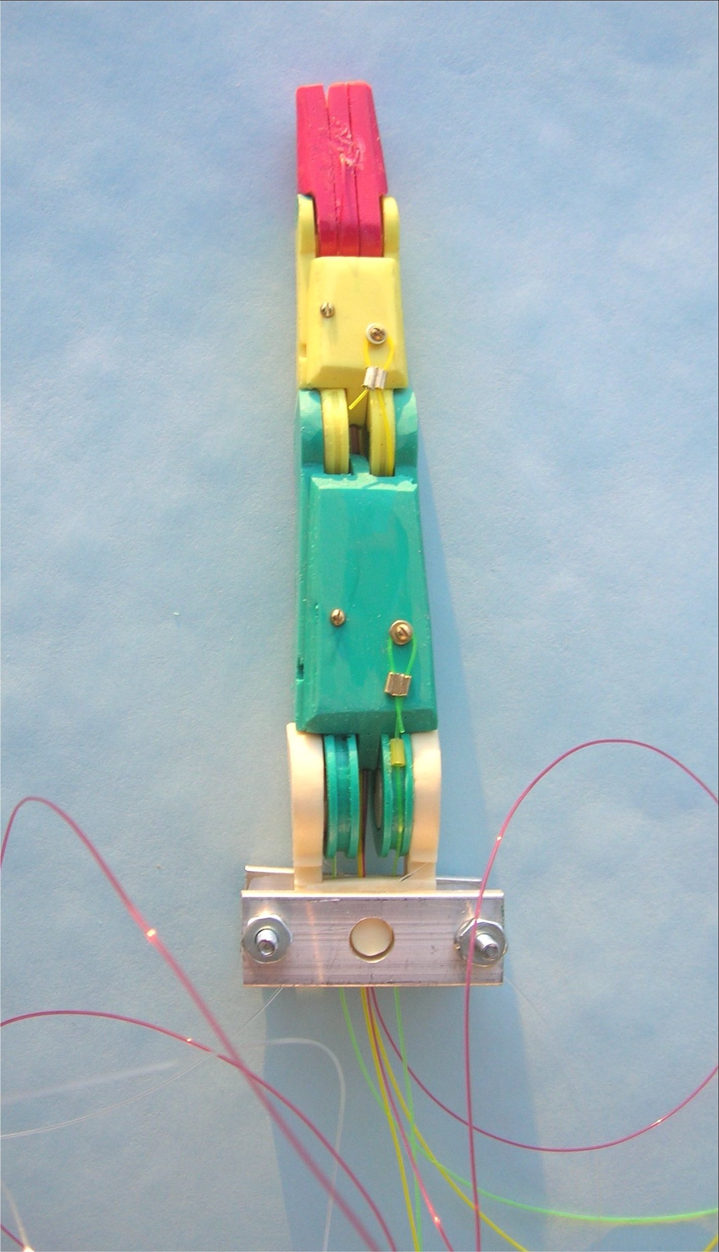
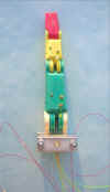
9. Adding the mounting. Refer
to the following picture.
- Assemble the mounting around the completed finger.
- Select one of your 1 3/8" aluminum bars.
- Select the two 4-40 screws 1 1/4 inch long.
- Insert them in the two 1/8 inch holes
- Select your two 15 mm 5/32 inch aluminum tubes. (* updated *)
- Slip them over the screws.
- Place the finger onto the bar so that the finger rests in the center hole.
- Select the other 1 3/8" aluminum bar.
- Place it on top of the spacers and over the top of the finger.
- Select the two lock washers and place them on top of the bar over each screw.
- Select the two 4-40 nuts and put one on each screw.
- Tighten down both screws.
- If your spacers are 15 mm long, the mounting will turn easily around the finger.
- YOU ARE DONE!
- Notice that the mounting screws are longer than necessary. This is to allow you to bolt them onto some other larger mounting of your own design.
- Alternate mountings.
- If you wish to mount several fingers together you will need to fabricate a mounting which curves so that the hand looks human.
- The important thing is to keep the 15 mm spacing between the top and bottom crossbars so that the fingers can move properly from side to side.
- This is of course the palm - which I do NOT have completed yet.
10. Operating your finger.
Obviously in order to operate your finger you will need to attach
the cables to some mechanism which will pull the cables.
These mechanisms may be servo motors (which I use) or perhaps
pneumatic cylinders. Theoretically you could operate all 8
cables with 4 servos, but this may prove difficult. You
may wish to use more. Also routing the cables through the
palm of the hand is a difficult problem which I am still working
on. There is a severe shortage of suitable tiny components.
|